
Reverse-engineering a closed embedded device — a GPON ONU, a router, an SBC of
unknown provenance — is mostly a loop: change something, see if the box still
works, and if it doesn’t, recover it and try again. The slow part is rarely the
thinking; it’s the plumbing. You need to watch the serial console, drive the
network, cut and restore power without walking to the bench, pull the flash back
out when a write goes wrong, and — on an optical device — sniff the bus that
tunes the laser. Do that by hand a few hundred times and the project dies of
friction.
So I built the plumbing into a single compact tool: one small box that binds every I/O line of the target and exposes them over SSH. After that, the whole
bring-up — including the parts a human would normally babysit — can be driven by
an AI that tests, reboots, and iterates on its own until the device works, and
the result is folded back into an open firmware anyone can build.
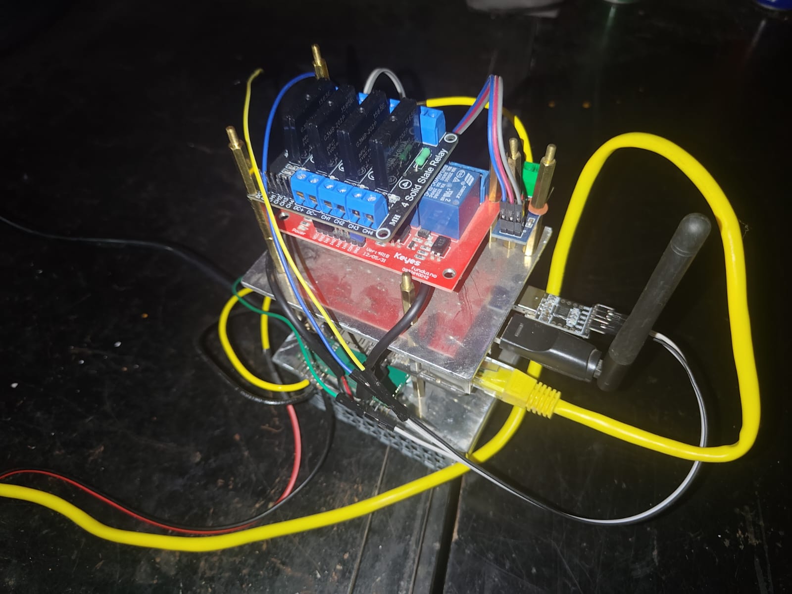
What’s in the box
A self-contained rig, small enough to sit next to the target:
| Part | Role |
|---|---|
| Odroid C2 (SBC) | The brain. Runs Linux, hosts TFTP/DHCP, serves the serial console and power control over SSH. Cheap, fanless, always-on. |
| USB Wi-Fi dongle | The client radio. Lets the rig see and join the target’s Wi-Fi AP from the outside — the only honest way to test that the AP actually works. |
| USB↔Serial TTL adapter | Taps the target’s debug UART (3.3 V TTL). The lifeline: U-Boot prompt, kernel log, recovery shell. |
| Mechanical relay | Switches the target’s low-voltage DC rail (the 12 V / 5 V barrel jack) for clean power cycling. |
| Solid-state relay (220 V) | For targets fed from mains (PSU brick, PoE injector, OLT-side gear): switches the AC side silently, with no contact wear. |
| Power supply | Feeds the Odroid and the switched rails. |
The Odroid is the only thing on the lab network. Everything downstream — UART,
Ethernet, power, radio, and the optical/diagnostic taps below — hangs off it, so
the entire bench is reachable through one SSH session.
  Lab network ── SSH ──> Odroid C2 ┬── USB-TTL ───────> target debug UART
                                   ├── Ethernet (end0) > target LAN port
                                   ├── USB Wi-Fi ······> target AP (over the air)
                                   ├── relay ─────────> target DC rail
                                   ├── SSR ───────────> target AC mains
                                   ├── I2C / logic ───> optical-module + probe taps
                                   └── fiber ──> splitter ──> OLT (for GPON range)
What it lets you do
By owning all of the target’s I/O at once, the rig closes every step of the
bring-up loop without a human in it:
- Test Ethernet end-to-end. The Odroid’s wired port is plugged straight into
the target’s LAN. Link up? DHCP lease? Ping both ways? Throughput? All
measurable from the host — no guessing whether the switch datapath actually
forwards frames. - Test the Wi-Fi AP for real. The USB radio scans, associates, and pushes
traffic over the air, exactly as a phone would. “The driver loaded” means
nothing; “a client got an IP and passed traffic” is the real pass/fail. - Boot a live system over U-Boot + TFTP. The Odroid runs a TFTP server (on a
RAM disk, wiped each reboot so it never fills up) and a small DHCP server.
Interrupt U-Boot over the serial line, hand the box an IP and a kernel +
rootfs, and it boots entirely from RAM — nothing touches the onboard flash.
You can iterate on a kernel a hundred times without ever risking the device’s
own firmware. - Power off/on to recover. This is what makes unattended work possible. When
a bad driver wedges the box — no console, no network, dead — the rig just cuts
power and brings it back. Combined with a watchdog (panic=+ reboot on hung
task), the target self-heals from almost any mistake, so the test loop never
stalls waiting for a human to flip a switch. - Dump partitions. Once a recovery shell is up (over UART or a TFTP-booted
live system), the flash partitions get read out over the wire — bootloader,
kernel, rootfs, calibration data. That dump is the raw material for the RE
below.
The design rule is conservative on purpose: don’t write the target’s flash.
Live-boot from RAM, experiment freely, and only commit an image to flash once it
has actually been proven on the bench. A read-only stance means a failed
experiment is one power-cycle away from a known-good state, not a brick.
The GPON-specific parts
A plain router needs Ethernet, Wi-Fi, power, and a console. A GPON ONU — the
fiber box at the end of a passive optical network — adds a whole second world
that the rig has to bind too, because almost none of it can be tested from a
desk in isolation. GPON is a shared, timed medium: the OLT (the operator-side
head end) broadcasts continuously downstream, and every ONU on the splitter must
transmit upstream only inside the burst window the OLT grants it. Get the
timing or the optics wrong and you don’t just fail — you stamp on every other
subscriber on that fiber. So the bench has to reproduce a real PON, safely:
- An OLT to range against. The rig drives a real (or lab) OLT over its
management channel — register the ONU’s serial number, watch it move through
the activation states, deactivate/reactivate it, and reboot it for a clean
slate. The ONU is meaningless without something on the other end of the fiber
expecting it. - Fiber + optical splitter (and attenuation). The ONU’s optical port goes
through a splitter to the OLT, the same topology as the field, so downstream
receive level and upstream burst timing behave realistically. - A tap on the optical module’s control bus. The transceiver — the BOSA, a
bidirectional sub-assembly carrying the laser (TX) and photodiode (RX) — is
configured over an I2C bus by the SoC. The rig taps that bus so it can read the
module’s live register state and watch how the stock firmware tunes it. - Downstream/upstream visibility. From the console and the SoC’s PON-MAC
state, the rig reads the activation FSM, receive-lock status, and the
message-level handshake, so each experiment has a concrete pass/fail instead of
just “link light is green.”
The hard problems unique to GPON, and why the rig matters for each:
- Laser ignition is delicate. The upstream laser must fire in burst mode,
only in the assigned slot. If it latches on continuously it blinds the shared
receiver and the link collapses — for everyone. You cannot debug this without
being able to observe receive-lock and instantly cut power; the rig gives you
both. - Activation is a protocol, not a wire. The ONU climbs an activation ladder
(initial → serial-number → ranging → operational). Ranging is the OLT
measuring the fiber round-trip and assigning the ONU its transmit offset.
Reaching the operational state is a software state machine reacting to
downstream messages — exactly the kind of thing you iterate on with live-boot
and instant recovery. - Management runs in-band. Once operational, the OLT configures the ONU over
a dedicated management channel carried inside its own encapsulated flow, with
upstream bandwidth governed by allocation containers. Getting that one flow
steered to the CPU — and answering it correctly — is its own sub-project, and
it only works if the rest of the datapath already forwards cleanly. - It has to survive the real world. The headline test isn’t first boot, it’s
recovery: pull the fiber, plug it back, and the ONU must re-range and come back
to service on its own. Reboot the OLT and it must follow. The rig scripts
exactly these events — fiber flap, power flap, OLT restart — and checks the box
heals every time.
The reverse-engineering process
These devices ship as a sealed black box: a stock firmware, a stripped
bootloader, and a SoC whose peripherals (the switch, the PON MAC, the radio, the
optics) are undocumented. Bringing up a clean, open firmware means recovering how
the hardware actually behaves and re-expressing that as new, mainline-style
code. With the rig in place, that’s a methodical loop:
- Capture the reference. Boot the stock firmware and record everything the
rig can see: the full serial log, U-Boot environment and commands, the
partition dumps, the device’s network behavior, and — where a debug shell
exists — live register and hardware state while the box is working. - Observe the working hardware. With the device known-good, read out the
state that matters: how the switch ports are configured, how the radio’s
analog front-end is tuned, what the optical module’s registers hold once the
link is up, what the PON MAC reports through ranging. These are facts about the silicon — addresses, fields, sequences, the order operations happen in. - Re-express, clean-room. Write fresh, idiomatic mainline drivers from those
observed facts. Nothing is copied; the behavior is reproduced. A measured
register sequence becomes new code with its own structure and licensing. - Prove it on the bench. Live-boot the new image over TFTP and check it
against the reference behavior the rig already captured: does Ethernet
forward, does the AP carry a client, does the optical link come up and stay
up across a disconnect/reconnect? Diff the new device’s state against the
stock capture. Where they differ, go back to step 2.
The rig makes each iteration cheap and safe: every attempt boots from RAM, every
failure is recovered by a power-cycle, and every result is measured the same way
the reference was.
Reverse-engineering via electronic knowledge
Software RE only starts once you’ve earned access to the hardware, and that part
is pure electronics. Before any code runs, you read the board itself:
- Identify the silicon. Read the part markings, match them to families and
datasheets, and infer the architecture (MIPS, ARM), the memory map, and which
peripherals exist. The SoC, the flash, the RAM, the switch PHY, the Wi-Fi
module, and the optical transceiver each announce themselves on the PCB. - Find the debug port. A 3.3 V UART is almost always present as a 3–4 pad
header or test points. A multimeter finds ground and the 3.3 V rail; a scope or
logic analyzer on the remaining pads at boot reveals TX (the pad that bursts
ASCII). Probe the baud, clip on the USB-TTL adapter, and you have the console —
the single most valuable foothold on the board. - Classify the flash and read it. Package and markings distinguish SPI NOR
from parallel/NAND. With a recovery shell you dump it over the wire; failing
that, a clip on an SPI NOR chip reads it in-circuit (hold the SoC in reset so
it doesn’t fight the bus). Either way you recover the bootloader, kernel,
rootfs, and the per-board calibration data. - Trace the buses that carry the secrets. The interesting configuration —
switch setup, PHY tuning, and especially the optical module’s calibration —
travels over I2C/MDIO/SPI between the SoC and its peripherals. A logic analyzer
on those lines while the stock firmware brings the link up captures the exact
register writes the working device performs. That bus capture is the legitimate,
source-free way to learn the “golden” settings: you watched the hardware do it. - Know the power tree. Which rails feed what, where the resets are, what’s
safe to switch. This is what tells you the relay belongs on the DC barrel jack
and the solid-state relay on the 220 V mains feeding the PSU — and it’s what
keeps “cut power to recover” from also corrupting a flash mid-write.
In other words, the relay, the SSR, the I2C/logic tap, and the UART clip aren’t
accessories — they’re the electronic half of the reverse engineering. The rig
is the instrument that turns board-level observation into facts the driver work
can use.
Porting OpenWrt
The open firmware the whole effort produces is OpenWrt — the device joins its
build tree as a first-class target instead of staying a vendor one-off. Porting
is its own discipline, and the bench is what de-risks every step:
- Stand up a target/subtarget. Add the SoC family to OpenWrt’s tree:
architecture, CPU features, the base kernel config, and the image-build recipe.
Start from the closest existing target and pare it down to what the board
actually has. - Write the device tree. OpenWrt is device-tree driven, so the board’s
layout — CPU, RAM, the flash partition map recovered from the dump, the UART,
the switch and its port mapping, the optical and radio interfaces — is
described in a.dts. The partition offsets come straight from the flash dump;
the console node from the UART you found by probing. - Feed in the clean-room drivers. The mainline-style drivers written from the
observed hardware facts — Ethernet/switch, the radio, the PON MAC and optical
front-end — slot into the kernel build for the target. They’re the bridge
between “this register sequence makes the hardware work” and “OpenWrt brings the
interface up at boot.” - Match the boot flow. The stock U-Boot expects a particular image format and
load address (learned from its environment and the serial capture), so OpenWrt’s
image recipe is shaped to produce something the existing bootloader will load —
without touching U-Boot itself, which is the one thing a bad change bricks
beyond recovery. - Live-boot before you ever flash. Every iteration of the OpenWrt image boots
from RAM over TFTP first. Only once an image proves out — boots clean,
interfaces up, services running — does it become a candidate for the real flash,
and even then through OpenWrt’s ownsysupgradepath with a known-good
fallback. - Build the userspace. Network config (the switch as LAN bridge + WAN uplink),
DHCP/DNS, the firewall and NAT, and a LuCI web UI — plus, for the ONU, the
GPON-management userspace that answers the operator’s in-band configuration.
Each piece is verified on the bench the same way: real client, real traffic,
real fiber.
The payoff is that the device stops being a sealed appliance running mystery
firmware and becomes a documented, buildable, upgradeable OpenWrt platform — and
because the work lands upstream, the next board in the same family is a
fraction of the effort.
Reverse-engineering driven by AI
Here’s the part the rig was really built for. Because every input and output of the target is now a command on the Odroid — read the console, set the network,
cut power, restore power, boot an image, dump flash, join the AP, sniff the
optical bus, drive the OLT — the whole loop is scriptable. And anything scriptable
can be handed to an AI.
The model drives the bench directly:
- It reads the serial console to identify the SoC, watch the boot, and catch
panics. - It stages a kernel/rootfs and live-boots it over U-Boot + TFTP.
- It runs the tests — link, DHCP, ping, throughput, AP association, and, for
the ONU, optical receive-lock and the full activation-to-operational climb —
and reads the pass/fail back off the same wires. - It observes at the electronic level, reading register and bus state through
the same taps a human would scope, and diffing the new firmware’s behavior
against the captured stock reference. - When an experiment wedges the box, it power-cycles the target itself and
carries on. No human needed to un-brick a RAM-booted board; it just resets and
tries the next hypothesis. For the ONU it goes further — scripting fiber flaps
and OLT restarts to prove the box recovers, not just that it boots once.
So the loop runs unattended: form a hypothesis about a register or a sequence → write the driver change → live-boot it → measure → if it failed, recover and revise → repeat. The AI keeps going through that cycle — testing and rebooting
on its own — until the device genuinely works: Ethernet up, Wi-Fi serving
clients, the upstream optical link establishing and surviving a disconnect, the
management channel answered.
And the endpoint isn’t a one-off hack. Each behavior that’s been recovered and
proven on the bench is ported into clean, open-source code — mainline-style
drivers and an OpenWrt target anyone can build and run on the same class of
hardware. The compact rig turns a sealed black box into a documented,
reproducible, open platform, and it’s the thing that made the iteration fast
enough — and safe enough to run unattended — to get there.